
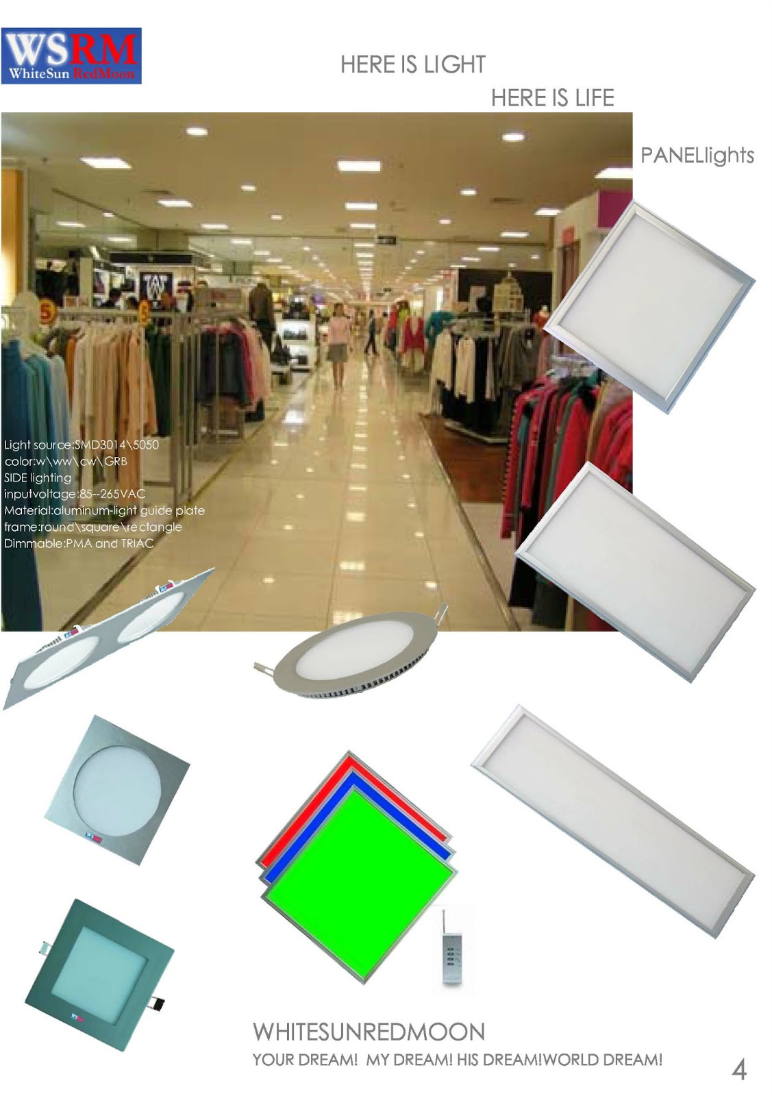
HERE IS LIGHT!HERE IS LIFE!
WSRM---LEDlights Application Notes!
Eye Protection - LEDs are very bright. DO NOT look directly into the LED light. The light can be intense enough to injure human eyes.

How does a LED work?
This is a very simple explanation of the
construction and function of LEDs. White LEDs
need 3.6VDC and use approximately 30 milliamps
of current, a power dissipation of 100 milliwatts.
The positive power is applied to one side of the
LED semiconductor through
a lead (1 anode) and a whisker (4). The other
side
of the semiconductor is attached to the top of the anvil (7) that is the
negative power lead (2 cathode). It is the chemical makeup
of the LED semiconductor (6) that determines the color of the light the
LED produces. The epoxy resin enclosure (3 and 5) has three functions.
It is designed to allow the most light to escape from the semiconductor,
it focuses the light (view angle), and it protects the LED semiconductor
from the elements. As you can see, the entire unit is totally embedded
in epoxy. This is what make LEDs virtually indestructible. There are no
loose or moving parts within the solid epoxy enclosure.
Therefore, a light-emitting diode (LED) is essentially a PN junction semiconductor diode that emits light when current is applied. By definition, it is a solid-state device that controls current without heated filaments and is therefore very reliable. LED performance is based on a few primary characteristics:

LED Colors
LEDs are highly monochromatic, emitting a pure color in a narrow frequency range. The color emitted from an LED is identified by peak wavelength (lpk) and measured in nanometers (nm ).
Peak wavelength is a function of the LED chip material. Although process variations are ±10 NM, the 565 to 600 NM wavelength spectral region is where the sensitivity level of the human eye is highest. Therefore, it is easier to perceive color variations in yellow and amber LEDs than other colors.
LEDs are made from gallium-based crystals that contain one or more additional materials such as phosphorous to produce a distinct color. Different LED chip technologies emit light in specific regions of the visible light spectrum and produce different intensity levels

Comparison of chip technologies for wide-angle, non-diffused LEDs
LED
Color | Standard Brightness | High Brightness | ||||||
| Chip Material | lpk (NM) | Iv (mcd) | Viewing Angle | Chip Material | lpk (NM) | Iv3(mcd) | Viewing Angle | |
Red
|
GaAsP/GaP
|
635
|
120
|
35
|
AS AlInGaP
|
635
|
900
|
30
|
Orange
|
GaAsP/Gap
|
605
|
90
|
30
|
AS AlInGaP
|
609
|
1,300
|
30
|
Amber
|
GaAsP/Gap
|
583
|
100
|
35
|
AS AlInGaP
|
592
|
1,300
|
30
|
Yellow
|
Gap
|
570
|
160
|
30
|
--
|
--
|
--
|
--
|
Green
|
Gap
|
565
|
140
|
24
|
GaN
|
520
|
1,200
|
45
|
Turquoise
|
--
|
--
|
--
|
--
|
GaN
|
495
|
2,000
|
30
|
Blue
|
--
|
--
|
--
|
--
|
GaN
|
465
|
325
|
45
|

White LED Light
When light from all parts of the visible spectrum overlap one another, the additive mixture of colors appears white. However, the eye does not require a mixture of all the colors of the spectrum to perceive white light. Primary colors from the upper, middle, and lower parts of the spectrum (red, green, and blue), when combined, appear white. To achieve this combination with LEDs requires a sophisticated electro-optical design to control the blend and diffusion of colors. Variations in LED color and intensity further complicate this process.

Presently it is possible to produce white light with a single LED using a phosphor layer (Yttrium Aluminum Garnet) on the surface of a blue (Gallium Nitride) chip. Although this technology produces various hues, white LEDs may be appropriate to illuminate opaque lenses or backlight legends. However, using colored LEDs to illuminate similarly colored lenses produces better visibility and overall appearance.

Intensity
LED light output varies with the type of chip, encapsulation, efficiency of individual wafer lots and other variables. Several LED manufacturers use terms such as "super-bright," and "ultra-bright" to describe LED intensity. Such terminology is entirely subjective, as there is no industry standard for LED brightness. The amount of light emitted from an LED is quantified by a single point, on-axis luminous intensity value (Iv). LED intensity is specified in terms of millicandela (mcd). This on-axis measurement is not comparable to mean spherical candlepower (MSCP) values used to quantify the light produced by incandescent lamps.

Luminous intensity
is roughly proportional to the amount of current (If) supplied to the LED. The greater the current, the higher the intensity. Of course, there are design limits. Generally, LEDs are designed to operate at 20 milliamps (mA). However, operating current must be reduced relative to the amount of heat in the application. For example, 6-chip LEDs produce more heat than single-chip LEDs. 6-chip LEDs incorporate multiple wire bonds and junction points that are affected more by thermal stress than single-chip LEDs. Similarly, LEDs designed to operate at higher design voltages are subject to greater heat. LEDs are designed to provide long-life operation because of optimal design currents considering heat dissipation and other degradation factors.
Eye Safety Information
The need to place eye safety labeling on LED products is dependent upon the product design and the application. Only a few LEDs produce sufficient intensity to require eye safety labeling. However, for eye safety, do not stare into the light beam of any LED at close range

Visibility
Luminous intensity (Iv) does not represent the total light output from an LED. Both the luminous intensity and the spatial radiation pattern (viewing angle) must be taken into account. If two LEDs have the same luminous intensity value, the lamp with the larger viewing angle will have the higher total light output.
Theta one-half (q½) is the off-axis angle where the LED's luminous intensity is half the intensity at direct on-axis view. Two times q½ is the LEDs' full viewing angle; however, light emission is visible beyond the q½ point. Viewing angles listed in this catalog are identified by their full viewing angle (2q½ °).
LED viewing angle is a function of the LED chip type and the epoxy lens that distributes the light. The highest luminous intensity (mcd rating) does not equate to the highest visibility. The light output from an LED chip is very directional. A higher light output is achieved by concentrating the light in a tight beam. Generally, the higher the mcd rating, the narrower the viewing angle.
The shape of the encapsulation acts as a lens magnifying the light from the LED chip. Additionally, the tint of the encapsulation affects the LED's visibility. If the encapsulation is diffused, the light emitted by the chip is more dispersed throughout the encapsulation. If the encapsulation is non-diffused or water clear, the light is more intense, but has a narrower viewing angle. Non-diffused and water clear LEDs have identical viewing angles; the only difference is, water clear encapsulations do not have a tint to indicate color when the LED is not illuminated.
Overall visibility can be enhanced by increasing the number of LED chips in the encapsulation, increasing the number of individual LEDs, and utilizing secondary optics to distribute light. To illustrate, consider similar red GaAlAs LED chip technology in four different configurations:

In each case, the amount of visible light depends on how the LED is being viewed. The single chip may be appropriate for direct viewing in competition with high ambient light. The 6-chip may be better suited to backlight a switch or small legend, while the cluster or lensed LED may be best to illuminate a pilot light or larger lens.

Operating Life
Because LEDs are solid-state devices they are not subject to catastrophic failure when operated within design parameters. DDP® LEDs are designed to operate upwards of 50,000 hours at 25°C ambient temperature. Operating life is characterized by the degradation of LED intensity over time. When the LED degrades to half of its original intensity after 50,000 hours it is at the end of its useful life although the LED will continue to operate as output diminishes. Unlike standard incandescent bulbs, DDP® LEDs resist shock and vibration and can be cycled on and off without excessive degradation.
Voltage/Design Current
LEDs are current-driven devices, not voltage driven. Although drive current and light output are directly related, exceeding the maximum current rating will produce excessive heat within the LED chip due to excessive power dissipation. The result will be reduced light output and reduced operating life.
LEDs that are designed to operate at a specific voltage contain a built-in current-limiting resistor. Additional circuitry may include a protection diode for AC operation or full-bridge rectifier for bipolar operation. The operating current for a particular voltage is designed to maintain LED reliability over its operating life.

Precautions While Working With LEDs
General
We cannot assume any responsibility for any accident or damage caused when the products are used beyond the maximum ratings specified herein. These pages are for information only and are the user assumes all responsibility and risk.
The user of these products must confirm the performance of the LEDs after they are actually assembled into the user's products/systems. It is strongly advised that he user design fail-safe products/systems. We will not be responsible for legal matters which are caused by the malfunction of these products/systems.
Static Electricity and Surge
Static electricity and surge damage LEDs. It is recommended to use a wrist band or anti-electrostatic glove when handling the LEDs. All devices, equipment and machinery must be electrically grounded.
 LEAD Forming:
The leads should be bent at a point at least 3mm from the epoxy resin of the LEDs.
Bending should be performed with the base firmly fixed by means of a jig or radio pliers.


Mounting Method:
The leads should be formed so they are aligned exactly with the holes on the PC board. This will eliminate any stress on the LEDs.

Use LEDs with stoppers or resin spacer to accurately position the LEDs. The epoxy resin base should not be touching the PC board when mounting the LEDs. Mechanical stress to the resin may be caused by the warping of the PC board when soldering. The LEDs must not be designed into a product or system where the epoxy lens is pressed into a plastic or metal board. The lens part of the LED must not be glued onto plastic or metal. The mechanical stress to the leadframe must be minimized.

Soldering
Solder the LEDs no closer than 3mm from the base of the epoxy resin.
For solder dipping, it may be necessary to fix the LEDs for correct positioning. When doing this, any mechanical stress to the LEDs must be avoided.
When soldering, do not apply any mechanical force to the leadframe while heating.
Repositioning after soldering must be avoided.
| Soldering Iron | Dip Soldering | Reflow Soldering | |
|---|---|---|---|
| Lamp LED |
300degC(max), 3sec(max)
|
260degC(max), 5sec(max)
|
Not allowed.
|
| Chip LED |
300degC(max), 3sec(max) with Twin Head iron
|
Not allowed.
|  |

Cleaning
Avoid exposure to chemicals as they may attack the LED surface and cause discoloration. When washing is required, "isopropyl alcohol" is to be used.
The influence of ultrasonic cleaning on the LEDs differs depending on factors such as oscillator output and the way in which the LEDs are mounted. Therefore, ultrasonic cleaning should only be performed after making certain that it will not cause any damage.
Emission color
LED emission wavelengths vary. LEDs are classified by emission color into different ranks. When a large volume of LEDs are purchased, LEDs with different color ranks will be delivered
Packaging
The leadframes of the LEDs are coated with silver. Care must be taken to maintain a clean storage atmosphere. If the LEDs are exposed to gases such as hydrogen sulfide, it may cause discoloration of the leadframes.
Moistureproof packing is used to keep moisture away from the chip type LEDs. When storing chip type LEDs, please use a sealable package with a moisture absorbent material inside.
LED Cluster Lamp and LED Dot Matrix Unit
Assembly
Please refer to the recommended distance between the leads when designing lead holes on the PC board.
Close attention must be paid on the correct positioning of O-rings and other water proof seals when assembling products/systems.
LEDs are vulnerable to static electricity. When handling the LEDs, necessary precautions regarding static electricity must always be taken into consideration.

Installation of LEDs
Make certain that the lead position and polarity are correct when installing the LEDs.
The interface cable must be as short as possible.
The power supply and ground line must be selected according to their current capacity.

Heat Dissipation
When many LEDs are mounted into a small area, heat generation must be taken into consideration. If there is a possibility that the ambient temperature may exceed 60 degrees centigrade, some kind of forced cooling system will be needed
The ambient operating temperature must be taken into consideration when a product/ system is being designed. There are certain limits to maximum current, at certain temperatures which must be kept in mind.
Handling
When the surface of the LEDs must be cleaned, the LEDs should be wiped softly with detergent. The surface may be damaged and the effect of the lens may be reduced with violent scrubbing.
Others
EMI countermeasures must be taken as a system.
When instantaneous power failure, or a current surge by lightning stops the controller at abnormal conditions, the abnormally high electric current may continue running through the LEDs for an extended period of time. This can damage the LEDs in the system. Circuit protection against abnormally high current must be built into the system to protect against this.
http://zgledn.yglm.mobi/
SALES CONTACT
ITALY
Torino
39011redmoon1@myledonline.com
Rome
3906whitesun1@myledonline.com
SPAIN
Barcelona
3493redmoon1@myledonline.com
GERMANY
Berlin
4930whitesun1@myledonline.com
FRANCE
Paris
331redmoon1@myledonline.com
ENGLAND
London
4420whitesun1@myledonline.com
RUSSIA
Moscow
7499redmoon1@myledonline.com
FINLAND
Helsinki
3589whitesun1@myledonline.com
NORWAY
Oslo
47whitesun1@myledonline.com
AUSTRIA
Vienna
431whitesun1@myledonline.com
NETHERLAND
Amsterdam
3120whitesun1@myledonline.com
SWITZERLAND
Zurich
4144whitesun1@myledonline.com
TURKEY
Istanbul
90216whitesun1@myledonline.com
BELGIUM
Brussels
322whitesun1@myledonline.com
SWEDEN
Stockholm
468whitesun1@myledonline.com
HUNGARY
Budapest
361whitesun1@myledonline.com
SCOTLAND
Glasgow
44141whitesun1@myledonline.com
ICELAND
Reykjavik
354whitesun1@myledonline.com
No comments:
Post a Comment